This blog is used to introduce the process of the year two project. The project is “Robot for remote monitoring”.
Introduction
- The project is about robot for remote monitoring, simply speaking is a vehicle with a weather station on it. And the robot can send the weather station to the specific place to do the measurement and collect the data then go back with the data.
First week
Week’s activities
Assemble the new smart car


Write a Arduino program and find the example programs for mBot to test the vehicle
Problem, issues and concerns
- How to collect the data and store?
- Transmission methods
Tasks for next week
- Data collecting methods and storing methods
- Transmission methods
Second week
Week’s activities
Looking for the method for the measurement
- Using the Arduino UNO board for the base of the weather station.
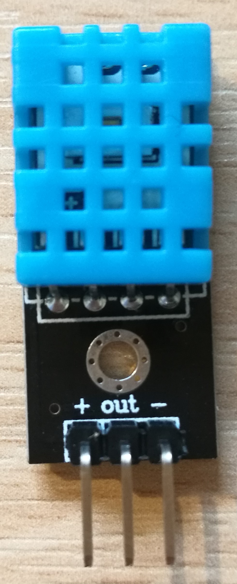
- Using the sensor DHT11 for the temperature and humidity measurement.
- Using the sensor TSG813 for the measurement of the methane($CH_4$)
- Using SD card to store all the data measured by the sensor
Create the website for the blog
- Website:The-year-2-project

- Website:The-year-2-project
Problem, issues and concerns
- Where should the blog be written at and what’s the format for blog?
- lacking for sensor and how to program them in the Arduino.
- Learning about the sensor DHT11 and TGS813, different units of the temperature measurement and the other concept of the humidity measurement such as dew point.
Tasks for next week
- Sensor connection with embedded system
- Data collection and synchronization of robot with sensor system
Third week
Week’s activities
- Connect the dht11 sensor and the microSD card module with the Arduino UNO board
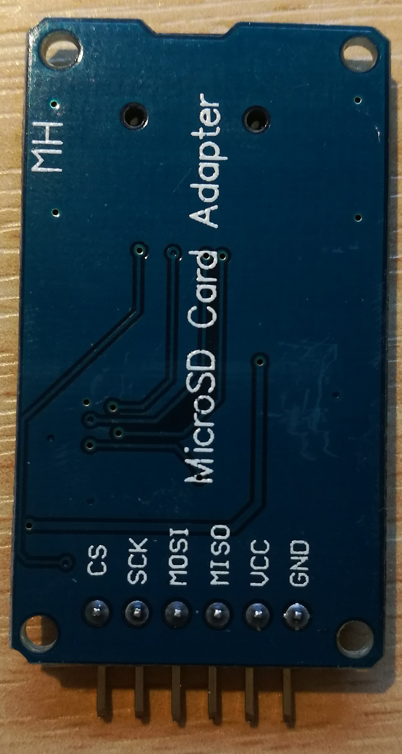
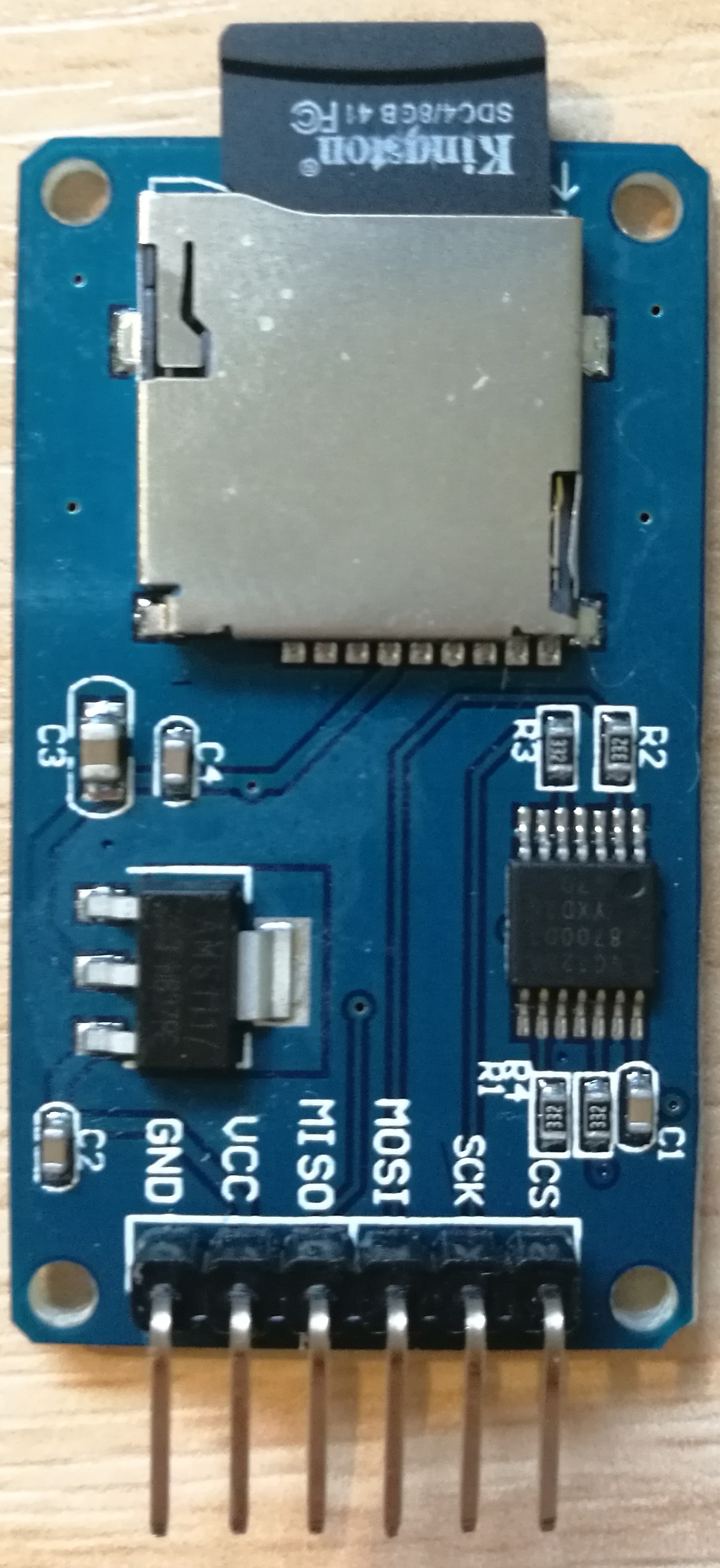

- Program the Arduino UNO board to see the data collected by the sensor and verify the SD module.
- The introduction of the dht11 module can be find on the Arduino official website, and the program can also be found on the website.
Project code of DHT11
1234567891011121314151617181920212223242526272829303132333435363738394041424344454647484950515253545556575859606162636465666768697071727374757677787980818283848586878889909192double Fahrenheit(double celsius){return 1.8 * celsius + 32;}double Kelvin(double celsius){return celsius + 273.15;}double dewPoint(double celsius, double humidity){double A0= 373.15/(273.15 + celsius);double SUM = -7.90298 * (A0-1);SUM += 5.02808 * log10(A0);SUM += -1.3816e-7 * (pow(10, (11.344*(1-1/A0)))-1) ;SUM += 8.1328e-3 * (pow(10,(-3.49149*(A0-1)))-1) ;SUM += log10(1013.246);double VP = pow(10, SUM-3) * humidity;double T = log(VP/0.61078); // temp varreturn (241.88 * T) / (17.558-T);}double dewPointFast(double celsius, double humidity){double a = 17.271;double b = 237.7;double temp = (a * celsius) / (b + celsius) + log(humidity/100);double Td = (b * temp) / (a - temp);return Td;}dht11 DHT11;void setup(){Serial.begin(9600);Serial.println("DHT11 TEST PROGRAM ");Serial.print("LIBRARY VERSION: ");Serial.println(DHT11LIB_VERSION);Serial.println();}void loop(){Serial.println("\n");int chk = DHT11.read(DHT11PIN);Serial.print("Read sensor: ");switch (chk){case DHTLIB_OK:Serial.println("OK");break;case DHTLIB_ERROR_CHECKSUM:Serial.println("Checksum error");break;case DHTLIB_ERROR_TIMEOUT:Serial.println("Time out error");break;default:Serial.println("Unknown error");break;}Serial.print("Humidity (%): ");Serial.println((float)DHT11.humidity, 2);Serial.print("Temperature (oC): ");Serial.println((float)DHT11.temperature, 2);Serial.print("Temperature (oF): ");Serial.println(Fahrenheit(DHT11.temperature), 2);Serial.print("Temperature (K): ");Serial.println(Kelvin(DHT11.temperature), 2);Serial.print("Dew Point (oC): ");Serial.println(dewPoint(DHT11.temperature, DHT11.humidity));Serial.print("Dew PointFast (oC): ");Serial.println(dewPointFast(DHT11.temperature, DHT11.humidity));delay(2000);}
- Connect the dht11 sensor and the microSD card module with the Arduino UNO board
Reference: http://playground.arduino.cc/Main/DHT11Lib
Then some new conceptions came out when looking at the explanation of the dht11 program, such as dewpoint() and dewpointfast, which need further study with the given website.
http://wahiduddin.net/calc/density_algorithms.htm
http://en.wikipedia.org/wiki/Dew_point
http://www.colorado.edu/geography/weather_station/Geog_site/about.htm
Project code for testing the MicroSD Card Module
|
|
Project code for storing the data measured by DHT11
|
|
Bluetooth module
Then the Bluetooth module is integrated in the circuit as shown in the figure
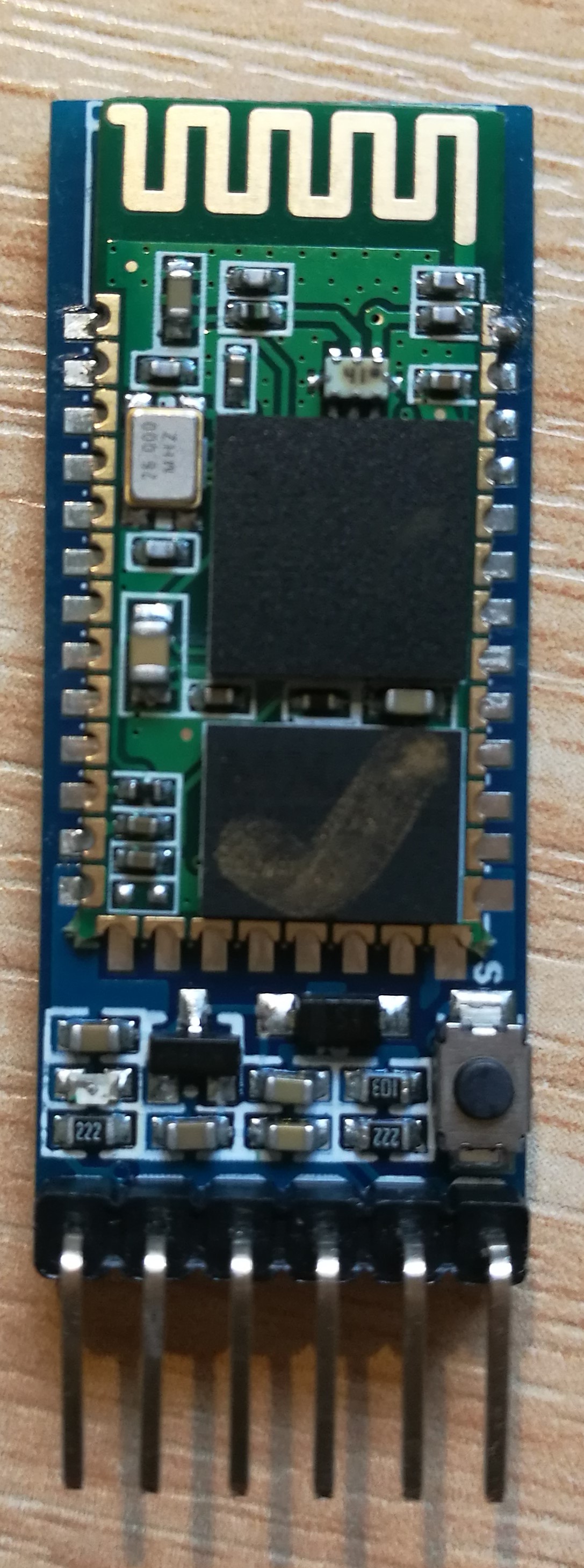

The Bluetooth module can be used to connect to the computer to measure the instant value.
Problem, issues and concerns
- Bluetooth module cannot work in AT command
- Gas sensor circuit’s build and programming
Tasks for next week
- Configuration and testing of sensor
Fourth week
Week’s activities
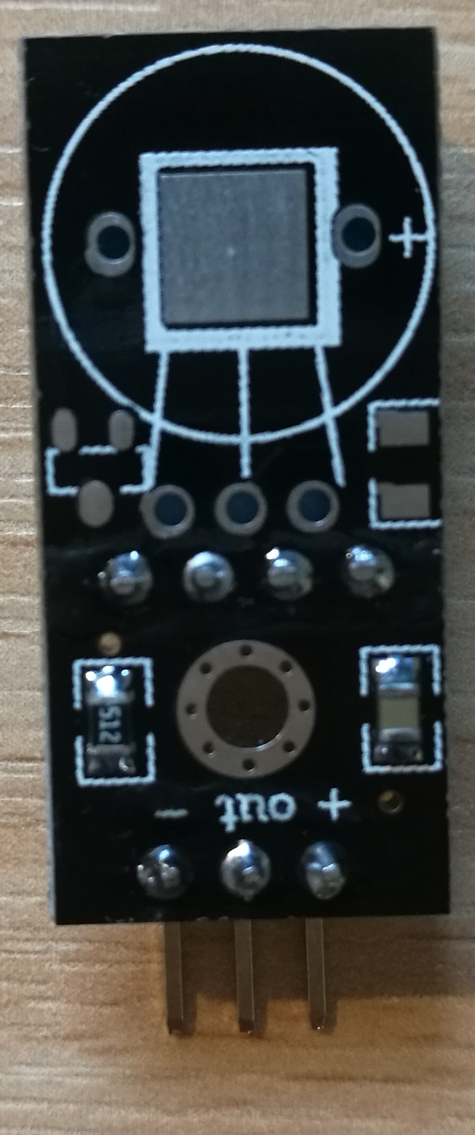
TGS813
This week the group members focus on the methane gas sensor TGS 813
Datasheet: http://www.figarosensor.com/products/813pdf.pdf
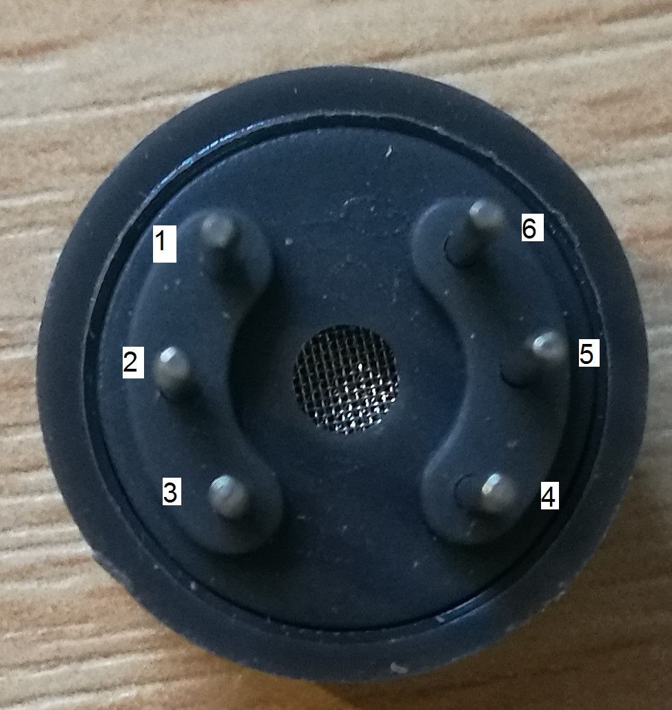
The pin numbers are shown in the second figure following
Pin 1 and pin 6 are two terminals of one sensor
Pin 3 and pin 4 are two terminals of one sensor
Pin 2 and pin 5 are two terminals of one heating component (heater)
The circuit is connected as the structure shown in the third figure
VRL is connected to the terminal A0 on the Arduino board to measure the change of the voltage.
The digital pin 8 of the Arduino is connected to the breadboard for the input voltage of the LED light. When the voltage measured is higher than 1V (this value can be change to adjust the sensitivity of the TGS 813) the digital pin 8 will be pulled high and the LED will light on.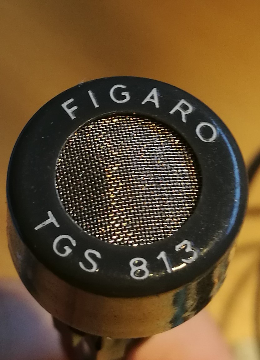

Project code of TGS813
|
|
Project code of storing the data measured by TGS813 and DHT11
|
|
Problem, issues and concerns
The connection between two parts by Bluetooth
Tasks for next week
- Configuring robot and communication between two parts (robot and station)
- Blog
Fifth week
Week’s activities
The car was programmed to send the weather station to the specific place
The car has two mode:
- Go and back with specific route
- Go following a line
Project code for mBot (Vehicle)
|
|
AT mode of Bluetooth module
Before the Bluetooth module begin working, push the button switch and pull pin 34 voltage high by wiring to Vcc. Then the Bluetooth module enter the AT command mode.
The light should be flashed slowly.
The pin 34 should be voltage high all the time to ensure Bluetooth is in “full” AT mode. If the pin 34 return the voltage low after Bluetooth is working, it will enter a mode named “mini” AT mode, in which some commands will fail.
Project code for AT mode
|
|
For the Bluetooth on the vehicle the group cannot enter the AT mode until the end of the lab day, so it’s a disadvantage that the weather station and vehicle cannot synchronize.
Then the vehicle and weather station can be considered as two individual part except the power supply.
Reference:
- http://www.martyncurrey.com/
- http://www.martyncurrey.com/arduino-with-hc-05-bluetooth-module-at-mode/
Problem, issues and concerns
- The vehicle cannot enter the AT mode due to its special system although it is based on Arduino.
Tasks for next week
- Blog
- Poster